


I’m going to show you how to set up and use a patch bay to create customizable signal processing chains using hardware like mic pre-amps, EQs, compressors, reverbs, and delays.
A patch bay allows you to create custom audio signal routings. You connect your microphones, outboard gear, and audio interface to the back of a patch bay, and then create custom processing chains by forming connections between jacks on the front of the patch bay, using patch bay cables.

For example, you could use a patch bay to route the signal coming from a microphone into a mic preamp, through an outboard compressor, into your audio interface, and then into your DAW.
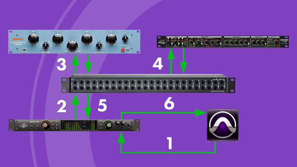
Alternatively, you could route audio from your DAW into an audio interface (1), then into a patch bay (2), through an outboard EQ and back into the patch bay (3), and then through an outboard saturator (4) and back into the patch bay. Finally, you could route the signal back into the audio interface (5) and then into your DAW (6).
There are two primary benefits to using a patch bay. The first is that it allows you to quickly create custom signal routings, without fumbling around behind your hardware, plugging and unplugging cables.
The second is that it prevents wear and tear on your hardware. Since you don’t typically unplug hardware from the back of your patch bay, unless you get new gear, the only cables and jacks that deteriorate over time are the patch cables and the jacks in the patch bay itself—which are both much cheaper to replace than the cables used to connect gear to the back of your patch bay, and the jacks in your hardware units.
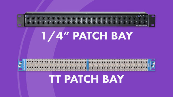
1/4” Patch Bays and TT Patch Bays
The two most common types of patch bays include 1/4” patch bays and TT patch bays. If you have a small home studio, I recommend you start off with a 1/4” patch bay; they’re much cheaper than TT patch bays, and no soldering is required to connect devices to the rear of the unit. The 1/4” patch bay that I use is the ART P48—it’s relatively cheap and it gets the job done.
Every patch bay setup is unique because it’s meant to cater to the particular gear that’s found within a person’s studio. I’m going to walk you through my patch bay setup to give you a general idea of how you may want to go about setting up your own patch bay. When you set up your patch bay, it’s probably going to look a little different since you likely don’t have the exact same gear that I do, but you can use my set up as a guide.
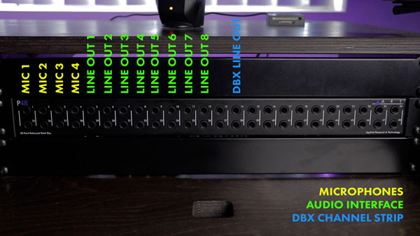
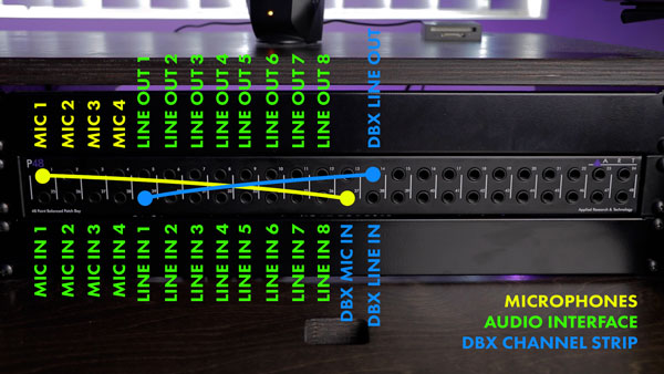
Every device that I own that produces a signal has been plugged into the top row of jacks on the back of my patch bay. This includes microphones, the line level outputs of my audio interface, and the line output of my DBX channel strip. If you own other external hardware, you would connect it’s outputs to the top row of jacks on the back of your patch bay.
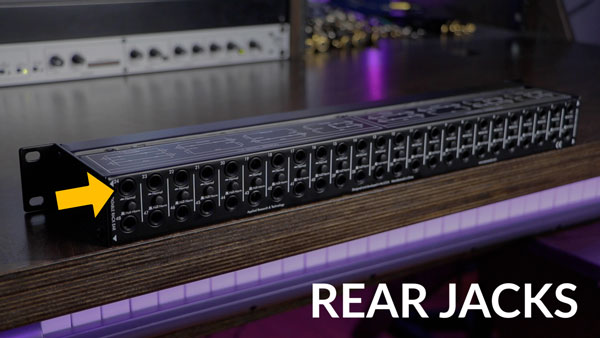
When a device produces a signal, it passes through the top row of jacks on the back of the patch bay to the bottom row of jacks on the back of the patch bay. If there’s a device connected to a bottom jack, it will receive the signal from the jack directly above it.
Normal Mode and Half Normal Mode
The big question is, “where do the front jacks come in?” Well, the front jacks are where you can create custom signal routings with cables, but each set of jacks will behave differently depending on the mode they’re in.


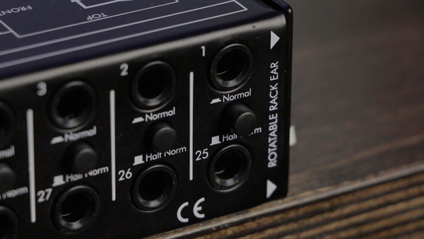
There’s a button between each top and bottom jack on the back of my patch bay that switches each set of jacks between a normal mode and half normal mode.
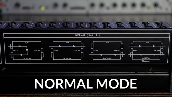
In normal mode, an audio signal running into a top rear jack will automatically run through to the bottom rear jack below it. If you plug an audio cable into the top front jack, you break this connection, and signal stops running down from the top rear jack to the bottom rear jack.
At this point, you can route the signal into another device connected to the patch bay. Once you’ve processed the signal you’ve sent off, you can route it back into the bottom front jack, which will pass it through to the bottom rear jack.
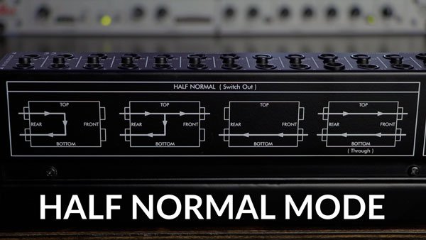
In half normal mode, you can plug an audio cable into a front panel top jack and send off or monitor the signal that’s flowing into the rear jack. In this case, the connection between the top jack and bottom jack is not broken.
I personally keep all my jacks in normal mode because I like being able to break my signal routings. For example, all my mics run directly into the mic inputs on my audio interface by default, when no cables are plugged into the front of my patch bay, which is convenient when I don’t want to apply processing on the way into my audio interface.
However, when I plug a patch bay cable into the top jack on the front panel of my patch bay, I break the default routing, which lets me route and process the signal through my DBX channel strip. Once I’ve processed the signal, I can route the DBX’s output signal into the input of my audio interface.
Basically my mic signal takes a little detour before reaching my audio interface. As you can see, it’s really quick and easy to set up alternative signal routings, and I’m sure your mind is now racing with all the signal routing opportunities available to you.
Using this patch bay set up, signal always runs from the top row to the bottom row by default, and every connection you make should be made between a jack on the top row and a jack on the bottom row. In this way, signal always cascades, or waterfalls, down the front panel of the patch bay.
If you ever find yourself trying to patch together two top row jacks, or two bottom row jacks, it’s a clear sign that you’re doing something incorrectly.
Simple enough, right? Signal from the top jacks runs down to the bottom jacks beneath them by default, and you can choose to create customizable signal processing chains using patch bay cables.
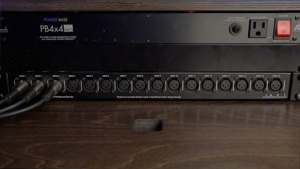
XLR Patch Bays
There’s one additional type of patch bay that I want to quickly mention, which is an XLR patch bay. You can connect the jacks on the back of this patch bay to the top row of jacks on your 1/4” patch bay—you'll need some female XLR to male 1/4" TRS adapters. This lets you plug in microphones and manipulate where their signal gets routed quite easily.


I have four microphones constantly hooked up to the back of my 1/4” patch bay because I use them all the time, but when I want to use a mic that I’ve rented, or a mic that someone’s brought over, I just plug it into the XLR patch bay, instead of rummaging around behind my desk.
It’s also worth noting that you can pass phantom power through a lot of patch bays, so you should have no problem recording with your mics that require an external power source.
My last piece of advice is to label your patch bay. I’ve added labels beneath the front panel of my patch bay to assist with keeping track of where my gear’s been plugged in, but you may just want to write it down on a piece of paper, or if you don’t have that much gear, you may not need to write it down at all.


