


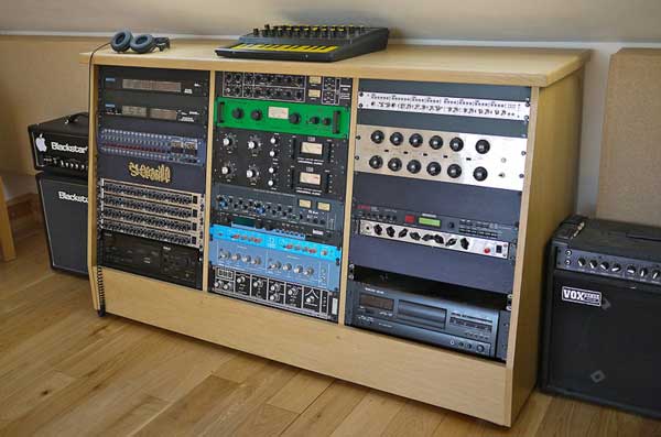
There’s nothing quite as exciting as walking into a studio packed to the brim with analog equipment. In today’s musical climate, you can make fantastic music using just your computer, but that doesn’t mean that outboard gear like hardware compressors, EQs, reverbs, delays, and mic preamps are irrelevant. There’s a sound quality, ease-of-use, and fun component associated with adding outboard gear to your studio; I’ll be showing you how you can effectively integrate this type of equipment into your existing setup.
Before catfishing you into rather expensive music production territory, I should mention that a lot of outboard gear is available in the form of analog-modeled plugins. Software manufacturers are now capable of recreating the sound of hardware processing units with pinpoint accuracy. The company modeling analog equipment the best, in my opinion, is Universal Audio with their UAD plugins. However, the caveat is that you need to own one of Universal Audio’s interfaces to run their plugins. Plugin Alliance, Slate Digital, and Soundtoys also make very powerful analog-modeled plugins, and they don’t require the use of dedicated hardware.
The keystone of a studio containing outboard gear is undoubtedly the audio interface. It converts analog signal to digital signal and vice versa, meaning you require an audio interface to connect analog equipment to your computer. Larger studios may actually need to use multiple audio interfaces depending on how much outboard gear they have.
An audio interface with many ins/outs will allow you to send signal to a substantial number of outboard units and record multiple tracks at once. At a minimum, you need an interface with two line outputs (on top of your main monitor outs) and two line inputs. This will allow you to take advantage of either two pieces of mono outboard gear, or one piece of stereo outboard gear; the left channel and right channel each require their own input/output. Unfortunately, the wildly popular Scarlett 2i2 will not allow you to use outboard gear because it only has two outputs for your monitors.
Instrument Level, Mic Level, and Line Level Signal
There are 3 different levels of analog signal that you’ll be commonly working with. Instrument level signal is produced by guitars and basses and mic level signal is generated by microphones; these types of signals need to be amplified to line level signal before getting run through outboard devices like compressors, EQs, saturators, etc.
You can bring an instrument level signal up to line level by either running it through a standalone DI box or running it through one of the HI-Z (high impedance) inputs on your audio interface. To bring a microphone’s signal up to line level, you’ll need to run it through a mic preamp. Your audio interface likely has at least a couple of built-in mic preamps, so a standalone preamp probably isn’t required.
For example, on my Apollo x8, there are 2 Hi-Z inputs, 4 microphone inputs along with 4 built-in mic preamps, and 8 line level inputs. This means I can connect 2 guitars, 4 microphones, and 4 line level signals at once. The microphone inputs are switchable with the first 4 line inputs, so I can potentially record 8 line level signals at one if I choose not to connect any microphones.
Using a Single Piece of Outboard Gear
Integrating a single piece of outboard gear into your studio is a simple process. To start, you run line level signal from your audio interface to the input(s) of the outboard gear. Then, you run the processed signal from the output(s) of your outboard gear to the input(s) of your audio interface. This set up assumes that you’re working with an audio signal that you’ve already recorded and that you want to process further using a single piece of outboard gear.
Using Multiple Pieces of Outboard Gear
It may seem like the number of pieces of outboard gear that you can use is limited based on the number of inputs your audio interface has. To some degree this is true, but by using a patch bay, you’ll be able to quickly switch between recording different pieces of gear, and chain audio devices together to perform serial processing.
You may be able to get away with resting a single piece of outboard gear on a desk, but you’re going to want to get your hands on a rack mount at some point. A rack mount allows you to screw your outboard gear into it, making it easy to store multiple hardware units near one another.
Patch Bays
A patch bay allows you to create custom audio signal routings. The two most common types of patch bays include 1/4” patch bays and TT patch bays. If you have a small home studio, I recommend you start off with a 1/4” patch bay; they’re much cheaper than TT patch bays, and no soldering is required to connect devices to the rear of the unit.
On top of allowing you to route audio signal in creative ways, patch bays prevent audio cable degradation; all the cables plugged into the rear of the unit are left in place. Connections are formed by plugging 1/4” patch bay cables into the 1/4” jacks on the front panel of the unit. The connections made on the back of your patch bay are permanent, while the connections on the front are temporary.
Patch bays may seem a little bit confusing at first, but they'll make complete sense once you wrap your head around the conept. The basic idea is that signal from your mics, preamps, line outputs, and audio devices run into the top rear set of jacks on your patch bay. By default, these signals flow through to the bottom rear jacks. The bottom rear jacks are where you connect the inputs of all your different audio devices. You can create your own custom signal paths by connecting top jacks to bottom jacks using patch cables on the front panel of the patch bay; doing this overrides the default cascading signal flow of the jack that you patch into.

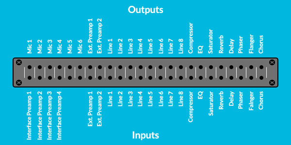
In Figure 2, the sound captured by Mic 1 will get routed to Interface Preamp 1 by default. If it helps, you can think of a patch bay like a waterfall; signal always runs downwards from the top jacks to the bottom jacks.
Suppose you want to run a mic level signal from Mic 1 to Ext. Preamp 1 instead of Interface Preamp 1. You can do this by connecting Mic 1’s output jack to Ext. Preamp 1’s input jack using a patch cable. Once you’ve brought the signal up to line level using Ext. Preamp 1, you’ll need to route it to one of your audio interface’s line inputs so that you can record it. To do this, use another patch cable to connect Ext. Preamp 1’s output jack to an available line input jack.
As you may have noticed, both of the connections that were just made involved connecting a top jack to a bottom jack. If you have a cable running from a top jack to a top jack, or a bottom jack to a bottom jack, you may be trying to patch devices together incorrectly.
Simple enough, right? The signals from the top jacks run down to the bottom jacks beneath them by default, and you can choose to route signals differently by connecting any of the top jacks to any of the bottom jacks using a patch bay cable. Knowing this, it makes sense to stack specific outputs on top of particular inputs.
I have my four most commonly used mic outputs stacked above my four available interface preamp inputs. This significantly reduces the number of patch cables I need to use because the mic signals flow into interface preamps by default. My two less commonly used mics (5 and 6) are off to the side, and their signals terminate themselves by default because there are no device inputs beneath them. I can still make use of mics 5 and 6 by patching them into my interface preamps; this will override the signal trickling down from the mic output above the interface preamp that I patch into. While I can have 6 mics patched into the rear of my patch bay, I can only record 4 of them through my interface preamps at once.
A patch bay doesn’t extend the number of tracks you can record, it just acts as a signal routing hub. Let’s say you’ve connected 16 different outboard audio effects to your patch bay and your audio interface only has 4 line inputs. This means you can just record 4 of those 16 devices at once. You can create processing chains that consist of more than one device, but you’d still be limited to recording 4 tracks simultaneously.
Normal Mode and Half Normal Mode
There’s one more patch bay feature you need to take into consideration. Most patch bays allow you to switch each set of jacks (top and bottom) between a normal and half normal mode. There are mode switches represented as orange dots in Figure 1 on the rear panel.
In normal mode, an audio signal running into the top rear jack of your patch bay will automatically run through to the bottom rear jack. If you plug an audio cable into the top front jack, you break this connection, and signal stops running down from the top rear jack to the bottom rear jack.
In half normal mode, you can plug an audio cable into a front panel top jack and send off or monitor the signal that’s flowing into the rear jack. In this case, the connection between the top jack and bottom jack is not broken.


When you plug a cable into a bottom front jack, the connection between the top jack and bottom jack is broken regardless of the mode you’re using. I prefer to set all my jacks to half normal mode because this allows me to audition signal between devices without affecting anything. I can connect my headphones directly to the device’s output without affecting the signal running down to the jack below it.
The way you decide to set up your patch bay is entirely up to you. Different studios will call for different patch bay configurations. What’s important is that your patch bay makes sense to you, and allows you to route audio effectively. Labeling your patch bay inputs/outputs with a label maker is an excellent way of keeping organized. I’ve placed a blank 1U panel above and below my patch bay which has given me the room I need to add labels.
In the following video, I demonstrate how to set up and use a patch bay.
Routing Audio to and from Hardware Within Your Daw
Let’s say you’ve captured a beautiful stereo recording of a guitar and afterward, you decide you’d like to run the recording through a pair of Teletronix 1176LNs, which are outboard compressors. I’ll be showing you how to route audio to outboard gear from within Ableton, but the general process will be relatively similar regardless of the DAW you’re using. If your audio interface comes with its own software that allows you to control the unit’s internal signal paths, I recommend returning these settings to default mode to avoid any sort of confusion once you connect the interface to a patch bay.
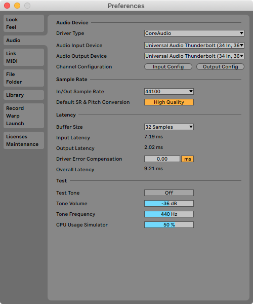
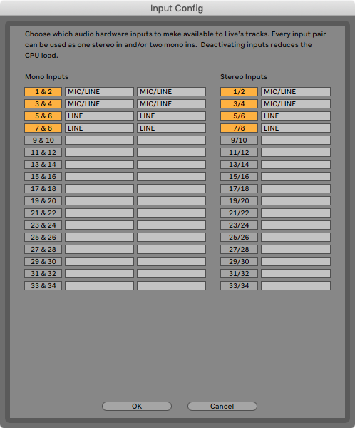
Ableton Live’s Audio Menu can be accessed via Live > Preferences… > Audio. Make sure that your audio interface is selected as both the Audio Input Device and the Audio Output Device. You’re going to want to access both the Input Configuration and Output Configuration menus from here; they’ll allow you to label all of your audio inputs and outputs.
On my audio interface, outputs 1 and 2 are for my main monitors, so I’ve labeled them accordingly. Outputs 3 and 4 are for lines 1 and 2, etc. If you permanently have an audio device connected to a particular output, it may be easier to just name the output after the device.
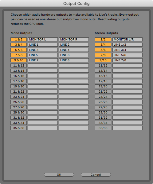
My mic/line inputs actually align with Ableton’s input numbering system, so I don’t need to add a number beside them like in the image above.
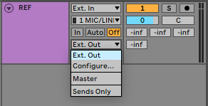
Now that you’ve set up the tricky part, you can head over to the Mixer section of the track you want to route to your outboard gear. Make sure that “Ext. Out” is selected from the Output Type dropdown menu.
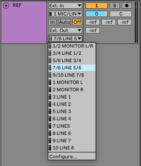
From the Output Channel dropdown menu below, select the output channel(s) that you’d like to use. Stereo channels are listed at the top of the dropdown menu and mono channels are listed towards the bottom. You’ll notice in the image below that Ableton’s Output Channel numbers are listed on the left, and my custom channel names are listed to the right. I'm going to select output channels 7/8, which correspond to my LINE 5/6 outputs.
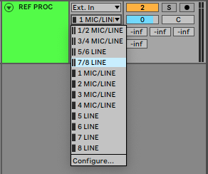
Once you've dialed in the settings on your outboard gear, you’ll need to record the processed signal back into your DAW. Create a new track and select “Ext. In” from the Input Type dropdown menu in the new track’s Mixer section.
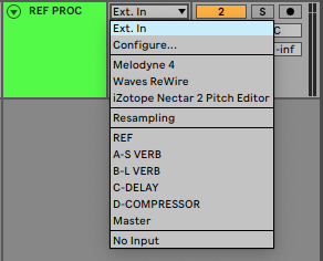
From the new track’s Input Channel dropdown menu, select the input channel(s) you wish to record. I patched my processed audio signal into lines 7 and 8 on my audio interface, so 7/8 LINE is the option I'll choose.
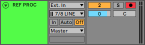
Set Monitoring to “Off” to avoid feedback and record-arm the track. When you’re ready to record audio through your outboard gear, press the Arrangement Record Button (at the top center of Ableton’s interface), engage playback, and then wait for the recording to finish.
Initially setting up your outboard gear can be quite time consuming and involve a fair bit of troubleshooting. For instance, when I set up my Apollo interface, I thought one of the line inputs was broken, but it turned out I was just using a defective patch bay cable. If you run into your own issues, start systematically testing each connection you’ve made, beginning at the sound source.
Working with outboard gear becomes quite an enjoyable experience once you get the hang of it. Using hardware processors isn’t quite as fast as using plugins, but there is definitely something unique about the tactile nature of analog equipment. Hopefully, this guide has helped open your eyes to some new signal routing possibilities.


